I made a capacitive water level sensor
■ Capacitive sensing
■ Build
■ Results
■ Future plans
For monitoring the water level of my rooftop water tank I have used a variety of different sensors. Requirement is to know the water level at any time, know the consumption over time, automate the pump in the future and possibly detect leaks and open pipes with some statistical analysis on the data points.
Initially it was just a resistor ladder with 10 steps. It was very reliable but the values will be in large steps like 10%..20%..30% etc. Then I switched to a cheap ultrasonic sensor. It worked until its transceivers got filled with water droplets due to high humidity. So I switched to a waterproof variant which is commonly used in vehicles for detecting objects in proximity while in reverse mode. But while monitoring the water level, sometimes its values will change erratically and trigger the notifications.
I recently found out that capacitive sensing is used for checking the liquid levels for weather data collection. And apparently it is very reliable. So I thought I will jerry-rig one. This is not the first time I have played with capacitive sensing. A music instrument I made as my college project used the same technique to detect triggering of a note and to measure how fast the note was played. It just had a steel bolt as the sensing point. But for the tank I will need a different form of this.
Capacitive sensing
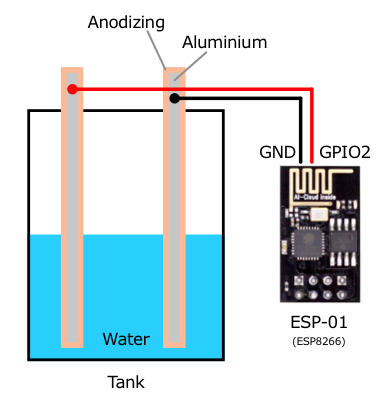
Capacitive sensing means measuring capacitance between two electrically conductive materials separated by a dielectric, something that is not conductive. Different dielectric materials have different capacitance. Air has lower capacitance and water has higher capacitance.
So if we have two insulated metal rods dipped in water then capacitance between them will be proportional to the water between them. So, as the water rise in level we will get a higher reading. Bit of Googling showed that most people are coating the metal with epoxy resin. But from my experiments an Aluminium wire with Anodizing works too. So my plan was to do something like this:
Build
I bought this anodized Aluminium wire from Amazon.
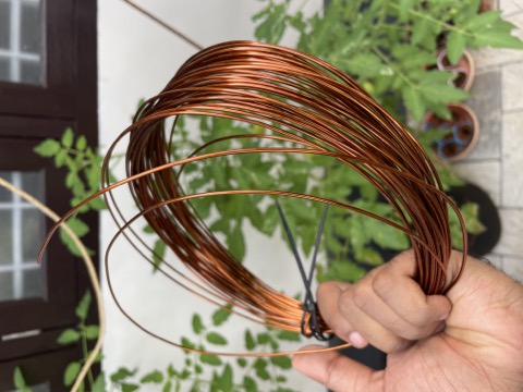
This is sold as Bonsai wire and I bought it for trellising Tomato plants in the background. First I cut small pieces and dipped in a water bottle to test out if it works. And they did reasonably well.
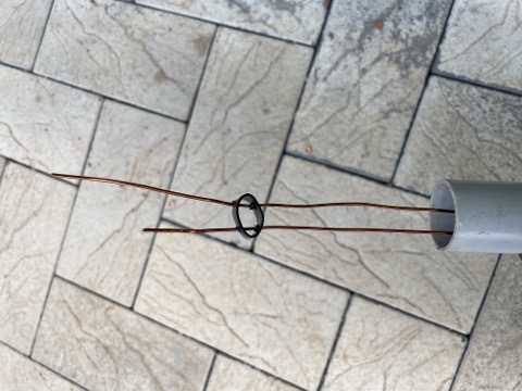
Next challenge was to keep two long wires at equal distance throughout the depth of the tank. I had these drip irrigation pipes that can be punctured easily and had the diameter same as the space I wanted between the wires.
![]()
So I cut these small circles off the pipe and punctured holes and fed the wire through.
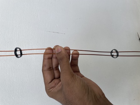
They are not in perfect spacing all the way, but they are perfect enough. Here is how it looks after all the spacers added:
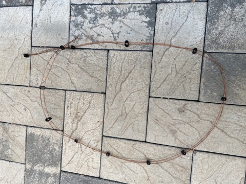
Then I enclosed this inside a PVC pipe:
And then at the other end where the wires will have exposed Aluminium I used epoxy glue to keep it in place and avoid electrical connection though water.
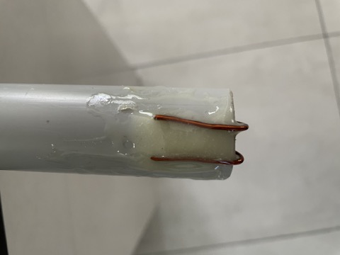
I let it dry for a day because I have heard they are slightly toxic until they are fully set. After that I installed it on the tank. I have a vertical steel tank and there is an air vent above it. I removed it and dipped this contraption through it.
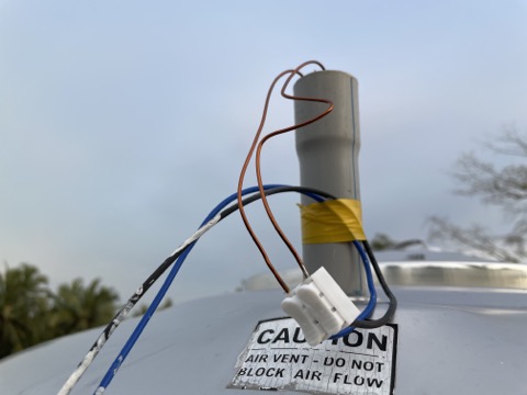
Yes, I read the warning and no, it doesn't block the air flow, there is a gap. There is still a chance that these connectors will get shorted temporarily when it rains. But that is a problem for another day.
I fed the wire below the tank where I keep my electronics. This contraption is kept inside an antistatic pouch and secured with electrical tapes. It is an ESP-01 module with ESP8266 WiFi chipset and an AMS1117 for regulated 3.3v for the module. It is powered from an old phone charger in my work area through a long cable.
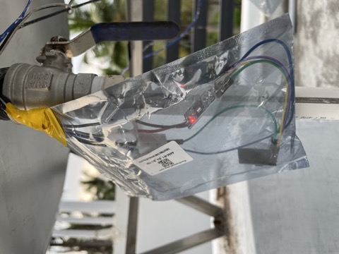
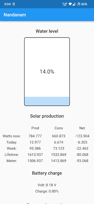
When powered on, it connects to my home WiFi, samples capacitance values for a second, calculates average, then dumps into InfluxDB hosted in my home server. I also have a Grafana instance to visualize data in InfluxDB. And I have built a Flutter app for monitoring different things in my house, including the water level. And it consumes InfluxDB via the json APIs. There is also a watchdog Go service running to check for the limits in the values, like below 20% water level, and send push notifications to the app.
Results
It kinda works. The value doesn't fluctuates erratically like with the ultrasonic sensor. But they are not super stable either. So I had to smooth the values further in InfluxDB so that it looks okay to the eye in the app. And the push notification to the app works reliably too.
Future plans
I'm gonna wait for a while and see if this is reliable enough to use it for automating the pump. If it is not good enough then I will have to keep the pump powered on for a specific amount time instead of stopping at a particular level the sensor reports.
I'm also planning to try different variations of the build. Such as:
- Aluminium plates or a wider strip instead of wires
- Reduce the gap between the electrodes
- 3D print the spacers to keep the distance between electrodes same
- More appropriate data smoothing function that considers the fact that the delta in the levels will be always small
I might also just abandon all of these ideas if I get lazy like how I'm while writing this article. But jugaad late night engineering will continue..